|
|
Post by matterbeam on Jul 20, 2017 2:17:04 GMT
We will look at how this critical component works and then at existing, future and possible designs.
Stefan Boltzmann
On Earth, heat leaves a vehicle through conduction, convection and radiation. In the vacuum of space, only radiation works to remove excess heat.

The International Space Station's radiators.
Spaceships are exposed to sunlight in space, which they absorb as heat through the hull. The various equipment on-board produces waste heat through their various inefficiencies, at different rates and temperatures. Even the crew contributes to producing waste heat. If this waste heat is not removed, it will accumulate and increase the spaceship's temperature until it melts. Radiators are critical for this reason.
Radiators work by emitting electromagnetic energy. It consists of photons of a wavelength determined by the radiator's temperature.

Guess what temperature this exhaust manifold is at.
Examples include the infrared wavelengths our body emits (300K), the red-orange visible wavelengths molten iron emits (1430K) and the bright white of the sun's surface (5800K).
For our purposes, we will focus on the energy removal capacity of a radiator. The rate is measured in watts: the waste heat watts absorbed and produced by the spaceship's systems, to be compared to the waste heat watts radiated away by a radiator. The relationship between the energy removal capacity and the radiator's temperature is given by the Stefan Boltzmann equation:
Waste heat removed: E * A * Sb * Temperature^4
E is the emissivity of the radiating surface. It is a property between 1 and 0. Extremely black surfaces approach 1 emissivity. Shiny surfaces have lower emissivity.
A is the surface area of a radiator, in square meters. Make sure to count it twice for a double-sided radiator.
Sb is the Stefan Boltzmann constant, equal to 5.67*10^-8.
Temperature is in Kelvin.
Design factors
Using the Stefan Boltzmann equation, we can quickly see that a radiator with better emissivity, higher surface area and higher temperature removes more waste heat.

On the left, 1100K radiators. On the right, 2700K radiators. The latter is actually handling three times as much waste heat.
On spaceships, it is important to use the lightest possible components for each task. A spaceship with lighter radiators will accelerate faster and have more deltaV, meaning it can go further and do more for less propellant.
If we want a lightweight radiator, we want it to have the highest emissivity. We can accomplish this by using naturally dark materials, such as graphite, or painting over shiny metals with black paint.
A larger radiator weighs more. We therefore want the smallest radiators possible. To compensate for lower surface area, we can increase the operating temperature. A small increase in temperature leads to a massive increase in waste heat removed. This means that hot radiators are massively lighter and smaller than cold radiators.
Further considerations

The ISS's EAC system
A typical radiator accepts coolant from a hot component. The coolant's component exit temperature is the initial temperature at the radiator. The radiator serves as an interface that radiates away the coolant's heat, leading to a lower radiator exit temperature. The coolant is fed back to the component to complete the waste heat removal cycle.
Note how the maximum temperature the heat exchanger's maximum temperature, delivered to the steam, is the lowest temperature of the liquid sodium in the reactor core.
Heat only flows from a hot object to a cooler object. A radiator can therefore only operate when the component's temperature is higher than the radiator's coolant exit temperature. For example, if a nuclear reactor operates at 2000K, the radiator must work at 2000K or less.

A reactor from COADE. The reactor operates at 2907K but the radiator receives coolant at 2400K.
The difference between the entry and exit temperatures in a radiator depends on many factors, but generally we want the largest difference possible. This difference in temperature is especially important for power generation. A large difference means more energy can be extracted from a heat source. It also means that less coolant is needed to cool a component.
This creates problems with realistic designs.
A general solution is to use two sets of radiators operating at different temperatures: one low-temperature circuit and one high temperature one. It works fine when your low temperature waste heat is a few kilowatts from life support and avionics. Other solutions have to be found for components that must be kept at low temperatures yet generate megawatts of waste heat, such as lasers.

This design has three sets of radiators of decreasing area for different temperature components.
For low temperature high heat components, heat pumps must be used. They can move waste heat against a temperature gradient, allowing, for example, a a 1000K radiator to cool down a 500K component. However, this costs energy. Moving heat from 500K to 1000K costs 1 watt to the pump for every watt moved. A realistic pump will not be 100% efficient and will require more than 1 watt to move a watt of waste heat.
Pump power: (Waste heat * Tc / (Th - Tc)) / Pump Efficiency
Pump power is how many watts the heat pumps consume. Waste heat is how many watts must be removed from the component. Tc is the component's temperature. Th is the radiator's temperature, both in Kelvins. Pump efficiency is a coefficient.

The refrigeration cycle is an example of a heat pump.
A coolant must generally be kept liquid. This imposes a lower and upper limit to the coolant temperature; any colder and it will freeze and block the pipes, any hotter it boils and stops flowing. Water coolant, for example, can only be used between 273 and 373K. More importantly, it limits the temperature difference that can be obtained from a radiator.
Large temperature differences require that the coolant spend a long time inside the radiator. This requires larger radiators or long, circuitous paths for the pipes. As the coolant becomes colder, it radiates at lower rates, meaning that the last 10 kelvin drop in temperature can take exponentially more time than the first 10 kelvin reduction. There are strong diminishing returns.
There are also structural concerns. Large temperature differences impose thermal stresses. These might be too great to handle. Lightweight, stressed radiators are prone to reacting badly to any sort of battle damage, making radiators a weak-spot for any sort of warship.

The ISS radiators' support spars. A spaceship under acceleration will need much more support.
All in all, we must keep in mind that there is a restricted range of temperatures between the hot and cold ends of a radiator, and that its performance cannot simply be obtained by using the Stefan Boltzmann equation on the maximum temperature. We cannot use a simple average either, because the coolant loses heat at a quadratically declining rate as it moves from higher to lower temperatures.
Here is an example of 1 kg of sodium at 1000K being cooled by a 0.8 emissivity one-sided 1m^2 radiator panel:

We can see that it takes 17 seconds for the sodium to cool down from 1000K to close to its melting point of 370K. Any cooler and it'll solidify in the pipes. If we average the radiated watts, we get a value close to 11.46kW. This corresponds to an average radiating temperature of 545K.
Finally, a radiator suffers stresses when a spaceship accelerates. Some types of radiator break or disperse under strong accelerations, so the spaceship's performance needs to be considered before selecting a design.
Solid Radiators

A straightforward design used today.
It consists of a slab of metal run through with hollow tubes for a coolant to flow. The waste heat conducts out of the coolant and into the radiator material, which radiates it away from its exposed surfaces.

This design has a rather high mass per area and low temperature limits, making it one of the worst performing designs. The maximum temperature is whatever keeps the radiator materials both solid and strong, which is important as many metals rapidly lose strength as they approach their melting point.
The coolant must remain liquid throughout the cooling cycle, so this limits the temperature difference that can be achieved. Using metals such as tin or salts such as sodium allows for better temperature differences, but pumping them requires specialized, sometime non-reactive, sometimes power consuming equipment.

Multiple radiators will shine their heat into each other and lose efficiency.
The arrangement of radiators around a spaceship must take into account inter-reflection, which is when one radiator's heat it intercepted and absorbed by another radiator. This reduces their efficiency. Anything more than two radiators per axis absorbs some of the heat of another radiator... at four radiators, only 70% of the heat escapes to space, at eight radiators, the efficiency falls to 38%.
NASA has studied solid radiators for use in its Nuclear Electric Propulsion concepts. It has specified 2kg/m^2 area density as a requirement for any thermal management system. The ISS's radiators mass 8 kg per square meter, or 2.75kg/m^2 if we only consider the exposed panels.
So far, only bare carbon fibre radiators operating at 800-1000K have reached this area density.
An alternative design achieves better area density by removing the coolant loops and pumps. The heat pipe has a hot end and a cold end, separated by a vacuum.

Heat Pipe moving waste heat into a heatsink.

Solid coolant is boiled away and then condensed on the cold end, then re-circulated through capillary action or centrifugal acceleration. This method allows for high operating temperatures and does not require any pumps of moving parts, but high mass per area negates many of its advantages.
On a warship, radiators are a weakpoint. Bright, exposed and hard to defend, they are easy to hit and once the are damaged, they can render a spaceship unable to function. They can mission-kill a warship without ever having to penetrate any armor. Redundant radiators impose a mass penalty. Covering the radiators in plates of armor massively decreases their thermal conductivity between coolant and exposed surfaces, which in turn reduces their efficiency.
Solutions for reducing the vulnerability of radiators include pointing them edge-on to the enemy, moving them to the back of the ship, or using retractable designs.

On the right, the radiators are exposed the enemy fire. On the left, the hull bulge protects the radiators from damage.
If all radiators are retracted, the spaceship must rely on heat sinks for its cooling needs. A megawatt heat source can boil off a ton of water in less than seven minutes, so this will only work over very short time periods.
A compact collapsible and retractable radiator design.
Read the rest in proper format, with in-text links, on the blog. |
|
|
|
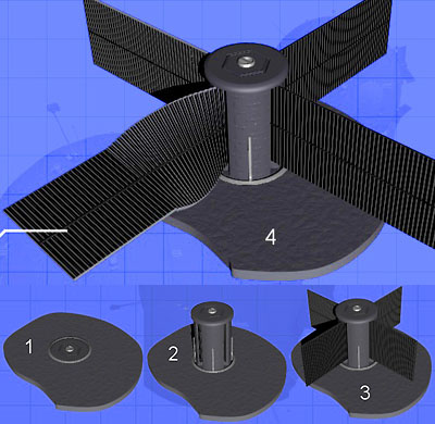
Post by Crazy Tom on Jul 20, 2017 16:42:18 GMT
My favorite types are solid mechanical radiators: 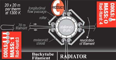 The one above uses carbon nanotube wires that have heat deposited into them by conduction when touching the rotating drum filled with hot coolant. I'm not sure if I would use them on a military warship due to how fragile they are and how they might get tangled when accelerating. Instead I would use a flat belt of high heat capacity material with a flexible heat resistant backing that rolls over two hot drums. You can poke holes in the belt, but it won't affect it much. The only issues would be nuke flash or long laser cuts. Droplet radiators are also very attractive for military designs if you can actuate the hot side sprayers so that the droplets are flung on a trajectory that accounts for the ship's acceleration and will see the droplets enter the collector at the end of their flight. This design is basically immune to ballistic, laser, or nuclear weapons, since the emitter and collector can be armored, and the 'radiator sheet' is just a bunch of droplets that can be replaced from internal stores without excessive mass penalty. |
|
|
|
Post by matterbeam on Jul 20, 2017 18:07:55 GMT
My favorite types are solid mechanical radiators: The one above uses carbon nanotube wires that have heat deposited into them by conduction when touching the rotating drum filled with hot coolant. I'm not sure if I would use them on a military warship due to how fragile they are and how they might get tangled when accelerating. Instead I would use a flat belt of high heat capacity material with a flexible heat resistant backing that rolls over two hot drums. You can poke holes in the belt, but it won't affect it much. The only issues would be nuke flash or long laser cuts. Droplet radiators are also very attractive for military designs if you can actuate the hot side sprayers so that the droplets are flung on a trajectory that accounts for the ship's acceleration and will see the droplets enter the collector at the end of their flight. This design is basically immune to ballistic, laser, or nuclear weapons, since the emitter and collector can be armored, and the 'radiator sheet' is just a bunch of droplets that can be replaced from internal stores without excessive mass penalty. I'm assuming that's the buckytube filament radiator. The high strength material is required to spin the loops at very high velocities, which allows for enough centripetal force to drown out deviations. I suggested a similar radiator where regular strength materials are instead guided by rollers and pulled along by motors. Wire guides and structural support is much more secure designs than free-falling loops. It will be heavier, but it might not be such a great concern. The other design you mentioned was the belt-loop radiator, or which I also drew a schematic. Again, it is heavier than the hula-hoop radiator, but can take up less space, which might be useful to warships who want to hide their radiating surfaces from enemy fire. Droplet radiators can be enclosed in transparent membranes. These will catch any droplets deviating from the path, rendering a moving collector arm unnecessary. It cannot be armored, but it can survive a lot of damage and is easily replaced. |
|
|
|
Post by apophys on Jul 20, 2017 20:00:17 GMT
If we want a lightweight radiator, we want it to have the highest emissivity. We can accomplish this by using naturally dark materials, such as graphite, or painting over shiny metals with black paint. How would this compare to optically transparent materials being used as a radiator? For example, synthetic gemstones like diamond? Theoretically, if you can get something transparent to a wavelength you radiate, you can radiate it from the entire volume. Would transparency always degrade with temperature? And a minor typo: |
|
|
|
Post by newageofpower on Jul 20, 2017 22:22:23 GMT
LDR collectors with extremely long coolant loops may prove difficult to armor, but even carrying extra collector armatures is likely to be orders of magnitude less than a solid radiator system. Droplet radiators can be enclosed in transparent membranes. These will catch any droplets deviating from the path, rendering a moving collector arm unnecessary. It cannot be armored, but it can survive a lot of damage and is easily replaced. Membranes that can withstand 2000k-3000k+ liquid metal droplets might be very massive and hence defeat the entire point of the LDR concept. |
|
|
|
Post by matterbeam on Jul 20, 2017 23:42:40 GMT
If we want a lightweight radiator, we want it to have the highest emissivity. We can accomplish this by using naturally dark materials, such as graphite, or painting over shiny metals with black paint. How would this compare to optically transparent materials being used as a radiator? For example, synthetic gemstones like diamond? Theoretically, if you can get something transparent to a wavelength you radiate, you can radiate it from the entire volume. Would transparency always degrade with temperature? And a minor typo: I think Kirchhoff's law of thermal radiation states that an object that radiates at a certain wavelength absorbs that wavelength equally well. So only the external surface of a 3D object is relevant for radiation. I might be wrong about this. I've fixed the typo, thanks. |
|
|
|
Post by matterbeam on Jul 20, 2017 23:49:59 GMT
LDR collectors with extremely long coolant loops may prove difficult to armor, but even carrying extra collector armatures is likely to be orders of magnitude less than a solid radiator system. Droplet radiators can be enclosed in transparent membranes. These will catch any droplets deviating from the path, rendering a moving collector arm unnecessary. It cannot be armored, but it can survive a lot of damage and is easily replaced. Membranes that can withstand 2000k-3000k+ liquid metal droplets might be very massive and hence defeat the entire point of the LDR concept. Another relevant fact is that of the volume occupied by the liquid droplet radiator, that can be fired upon, very little of it is physical objects. So the probability of enemy fire intercepting the emitter or collector arm is very low.... low enough perhaps to just use multiple un-armored arms and replace them when damaged. As for membranes, please note that most of the cooling happens in the first second after the droplet is released. Using this Hyperphysics calculator, I can get cooling time for spherical bodies composed of homogeneous atoms. If I input 0.5 micrometers radius of say, liquid tin at 2000K, and assume that some black ink is sprayed on by an inkjet to increase emissivity to 0.8, then I have the droplet temperature fall to 128K in a single second. The droplet will not travel far from the spray nozzle before it is cold enough to touch. |
|
|
|
Post by nerd1000 on Jul 23, 2017 2:34:42 GMT
I'm quite attracted to liquid drop radiators for sci-fi settings because of their (probable) appearance: They'd be like a waterfall of liquid fire. Even better, if you're aiming the sprayers to account for acceleration the drops will follow a curved path relative to the ship, which would look really fascinating.
|
|
|
|
Post by Enderminion on Jul 23, 2017 3:17:47 GMT
as matter beam said, I would rather have shorter spray tracks and higher mass/flow rates to get cooling
|
|
|
|
Post by apophys on Jul 23, 2017 5:53:43 GMT
I'm quite attracted to liquid drop radiators for sci-fi settings because of their (probable) appearance: They'd be like a waterfall of liquid fire. Even better, if you're aiming the sprayers to account for acceleration the drops will follow a curved path relative to the ship, which would look really fascinating. I'm thinking more along the lines of charged particles of carbon or tantalum hafnium carbide, as with the ETHER radiator listed in the version of the article on matterbeam's blog. That way they'd get pleasantly high max temperatures, they could be accelerated through their path for fast flow rates, and you wouldn't lose material to evaporation losses or strong/unexpected acceleration. You'd still get the same bright visuals and warping of the shape under acceleration, just somewhat confined instead of fully free-flowing. |
|
|
|
Post by matterbeam on Jul 23, 2017 9:39:08 GMT
I'm quite attracted to liquid drop radiators for sci-fi settings because of their (probable) appearance: They'd be like a waterfall of liquid fire. Even better, if you're aiming the sprayers to account for acceleration the drops will follow a curved path relative to the ship, which would look really fascinating. You'd get those long streams using larger particles. These take several seconds to cool down. However, their surface area to particle mass ratio is much smaller, so you'd end up with a less effective cooling system. On the other hand, there might be a minimum size to the droplets you can reliably form. |
|
|
|
Post by Rocket Witch on Jul 23, 2017 16:27:13 GMT
I'm thinking more along the lines of charged particles of carbon or tantalum hafnium carbide, as with the ETHER radiator listed in the version of the article on matterbeam's blog. That way they'd get pleasantly high max temperatures, they could be accelerated through their path for fast flow rates, and you wouldn't lose material to evaporation losses or strong/unexpected acceleration. You'd still get the same bright visuals and warping of the shape under acceleration, just somewhat confined instead of fully free-flowing. There is, by the way, a composite of hafnium, carbon and nitrogen that is predicted to have a melting point ~200K above THfC. I can't tell if this is the same thing as the ostensibly commercially available 'hafnium carbonitride' though. I'd like to mod it in but getting the (predicted) data seems an unlikely prospect, unless someusername6 can get something on it with their library card. Then we could use data modified or taken straight from regular Hafnium Carbide to fill in any blanks, I suppose. |
|
|
|
Post by someusername6 on Jul 23, 2017 20:32:08 GMT
I'm thinking more along the lines of charged particles of carbon or tantalum hafnium carbide, as with the ETHER radiator listed in the version of the article on matterbeam's blog. That way they'd get pleasantly high max temperatures, they could be accelerated through their path for fast flow rates, and you wouldn't lose material to evaporation losses or strong/unexpected acceleration. You'd still get the same bright visuals and warping of the shape under acceleration, just somewhat confined instead of fully free-flowing. There is, by the way, a composite of hafnium, carbon and nitrogen that is predicted to have a melting point ~200K above THfC. I can't tell if this is the same thing as the ostensibly commercially available 'hafnium carbonitride' though. I'd like to mod it in but getting the (predicted) data seems an unlikely prospect, unless someusername6 can get something on it with their library card. Then we could use data modified or taken straight from regular Hafnium Carbide to fill in any blanks, I suppose. The first thing I noticed is that literature does not seem to confirm the melting point of TaHfC from game -- the game puts it at 4488 K, while wikipedia puts it at 4201 K, with tantalum carbide having the 4488 K melting point instead (game puts it at 4150 K). Maybe that needs to be fixed? The supplementary data to that study (study is linked below, supplementary data requires subscription) puts the melting point at 4141 ± 21 K -- so still not over the 4488 K you want to go over. Here are the properties I did find, though, and references: Material Hafnium Carbonitrite
Elements Hf C N
ElementCount .53 .27 .20
Density_kg__m3 ??
YieldStrength_MPa ??
UltimateTensileStrength_MPa ??
YoungsModulus_GPa 260
ShearModulus_GPa ??
MeltingPoint_K 4141
SpecificHeat_J__kg_K ??
ThermalConductivity_W__m_K ??
ThermalExpansion__K 7.3e-6
Resistivity_Ohm_m ??
RefractiveIndex Hafnium
RoughnessCoefficient 0.5- Hong, Qi-Jun, and Axel van de Walle. "Prediction of the material with highest known melting point from ab initio molecular dynamics calculations." Physical Review B 92.2 (2015): 020104. link: authors.library.caltech.edu/59499/1/PhysRevB.92.020104.pdf
- Piedrahita, W. F., et al. "Evolution of physical properties in hafnium carbonitride thin films." Journal of Alloys and Compounds 690 (2017): 485-496.
- Aigner, K., et al. "Lattice parameters and thermal expansion of Ti (CxN1− x), Zr (CxN1− x), Hf (CxN1− x) and TiN1− x from 298 to 1473 K as investigated by high-temperature X-ray diffraction." Journal of alloys and compounds 215.1-2 (1994): 121-126.
|
|
|
|
Post by matterbeam on Jul 23, 2017 20:59:08 GMT
I'm thinking more along the lines of charged particles of carbon or tantalum hafnium carbide, as with the ETHER radiator listed in the version of the article on matterbeam's blog. That way they'd get pleasantly high max temperatures, they could be accelerated through their path for fast flow rates, and you wouldn't lose material to evaporation losses or strong/unexpected acceleration. You'd still get the same bright visuals and warping of the shape under acceleration, just somewhat confined instead of fully free-flowing. There is, by the way, a composite of hafnium, carbon and nitrogen that is predicted to have a melting point ~200K above THfC. I can't tell if this is the same thing as the ostensibly commercially available 'hafnium carbonitride' though. I'd like to mod it in but getting the (predicted) data seems an unlikely prospect, unless someusername6 can get something on it with their library card. Then we could use data modified or taken straight from regular Hafnium Carbide to fill in any blanks, I suppose. And graphene can survive nearly 5k temperatures. I think the issue in this case becomes finding components or reactors that run even hotter than this, so that the radiator can cool them. |
|
|
|
Post by apophys on Jul 24, 2017 2:44:41 GMT
I think the issue in this case becomes finding components or reactors that run even hotter than this, so that the radiator can cool them. There was an idea bounced around on the Discord channel for a boiling uranium reactor. Reactor chamber is liquid uranium at its boiling point; as it reacts and generates heat it boils. Gaseous uranium gets run through a steam turbine or MHD generator. Then it gets cooled and condensed back to liquid and returned to the reactor chamber. The boiling point of uranium is 4111 K according to CoaDE, so the vast majority of materials cannot contain this. A nice feature is that a criticality incident would just cause more vigorous boiling, instead of melting through the pressure vessel. Excessive pressure can, at worst, get vented. Having steamships in space is funny. |
|