Advanced Solar Energy in Space: Part II (TURBINES)
Dec 27, 2017 21:22:07 GMT
apophys, SevenOfCarina, and 4 more like this
Post by matterbeam on Dec 27, 2017 21:22:07 GMT
I share with you my study on turbines and the specific power densities that could be achieved.
Advanced Solar Energy in Space: Part II
Brayton cycle
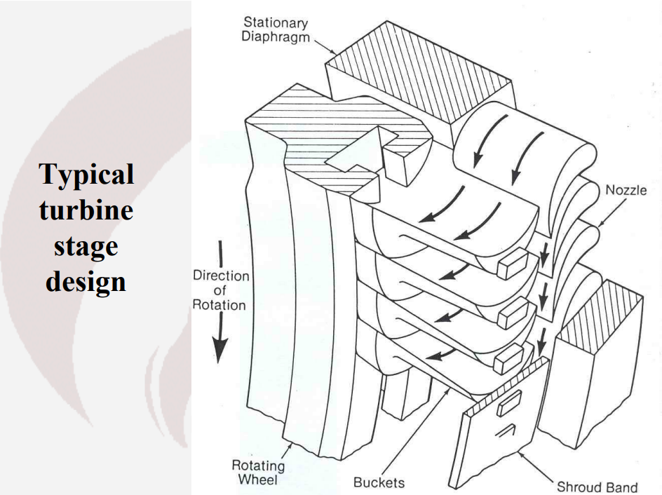
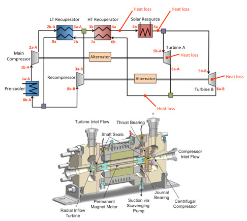
We commonly see the Brayton cycle used to convert heat into work in jet engines and the steam turbines of power plants. There are three main components: a compressor, a heat exchanger and a turbine. Gas is compressed to a high pressure by the compressor, then is heated by the heat exchanger. The turbine expands this gas to convert its energy into the mechanical rotation of the turbine's shaft. The latter is used to compress more gas, with the energy remaining able to be put to work. In a power plant, the remaining energy is used to spin an alternator to generate an electric current. Together, this forms a Brayton-cycle turbo-generator.
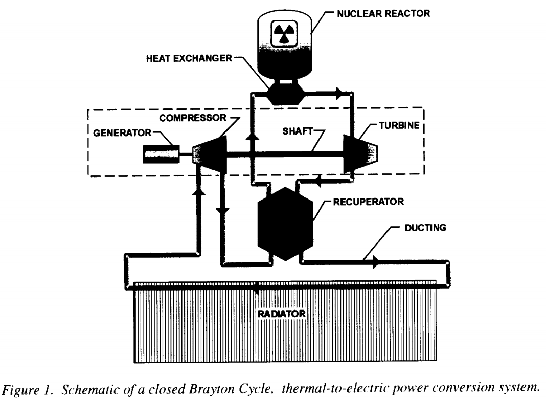
A closed cycle gas turbine adds an additional step: the exhaust gases released by the turbine are recycled back into the compressor. The gas is heated externally and is typically inert, as it is not being burnt up like in an open-cycle gas turbine. This makes it it ideal for space applications.
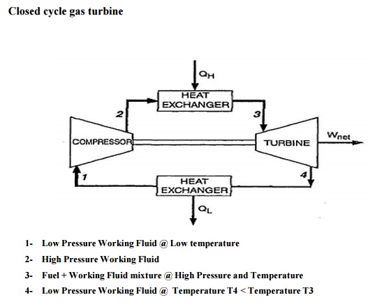
Let us have a look at the pressure and temperature conditions at each step of the closed Brayton cycle to understand where the turbine's power is coming from. We assume typical component efficiencies of 80% for the compressor and 90% for the turbine.
We will set Temp1 and Press1 as the temperature and pressure of the gas at the compressor's inlet. Temp 2, Press2 at the compressor's outlet, Temp3, Press3 at the turbine's inlet, Temp4, Press4 at the turbine's outlet. We will use example figures for these to make it easier to understand, in Kelvin and bars respectively. We will assume a monoatomic gas, such as helium, with a constant volume heat capacity of 3.12kJ/kg/K.

The gas starts at Temp1: 300K and Press1: 1bar. This is a warm gas at sea level pressure. It contains very little energy: 936kJ/kg.
The compressor raises the pressure to Press2: 10 bars. The gas's temperature increases by a factor determined by the following equation for isentropic expansion:
Inlet Temperature/Outlet Temperature= Pressure Ratio ^ (1 - 1/y)
The compressor increases the pressure tenfold, to the pressure ratio is 10. 'y' is the adiabatic gas constant. For simple mono-atomic gases, it is equal to 1.6.
We work out that the compressor increases the temperature by a factor 2.37. Temp2 is therefore 711K and the gas contains 2218kJ/kg. Due to the compressor's efficiency of 80%, this step consumes (2218-936)/0.8: 1602kJ/kg.
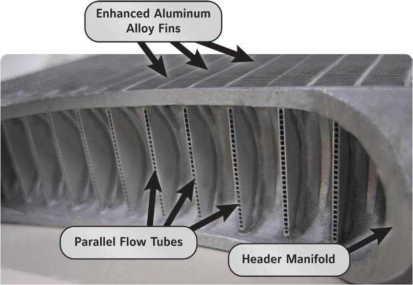
The gas then arrives at the heat exchanger. It is designed to heat up the gas at constant pressure. The gas exits the heat exchanger at Temp3: 1300K and Press3: 10bar, reaching 4056kJ/kg.The heat exchanger grants an energy increase of (4056-2218): 1838kJ/kg.

The turbine is the most critical component. Here, the gas is expanded back to a pressure of 1bar, so Press4: 1 bar. Isentropic expansion causes a temperature drop. Using the same equation as above, we know that a tenfold pressure decrease will reduce the temperature by a factor 2.37. Therefore, the gas exits the turbine at Temp4: 1300/2.37 = 548K. It falls to 1710kJ/kg. Because the turbine is 90% efficient, it extracts only (4056-1710)*0.9: 2111kJ/kg.
This is exhaust at Temp4 and Press4 must then be cooled down back to initial conditions, of Temp1 and Press1, using a radiator.
The find out the net energy extracted by the turbine, it is easiest to calculate the difference between the energy consumed by the compressor and the energy extracted by the turbine. This amounts to 2111-1602: 509kJ/kg.
Compare this to the energy granted by the heat exchanger to find the overall efficiency.
509/1838: 0.2777 or 27.8%
Technically, gas pressure also contains energy, but in a closed cycle, what is spent in the compressor to increase the pressure is regained in the turbine when it expands the gas.
To extract more power and increase overall efficiency, we can immediately understand that we need a higher temperature gradient. As we have seen in Part 1 of Advanced Solar Energy in Space, it is possible to design a heat exchanger that reaches thousands of Kelvin under concentrated sunlight. We will use this as the heat source for our space-based turbogenerator, as has been considered before by NASA.
However, we must make sure that the turbine blades are able to survive the Temp3 conditions. While there are many materials that do not melt even at very high temperature, there are few that remain strong enough to rotate at thousands of RPM without deforming under those same conditions.

Strength/Temperature curve for a Nickel superalloy.
Shown above is the yield strength of a Ni-Cr-W-Al-Ti-Fe-Si-C-B (Nickel, Chromium, Tungsten, Aluminium, Titanium, Iron, Silicon, Carbon, Boron) superalloy. It is designed to survive for 100000 hours under conditions of high stress (1000 bars) and high temperature (1023K). Looking at the graph, we notice that it retains most of its strength up to about 750oC, making it ideal for the conditions it was designed for. However, if we used it in the turbine we used as an example above, operating at 1300K (1027oC), it would have a strength reduced by over 80% compared to what it was designed for!
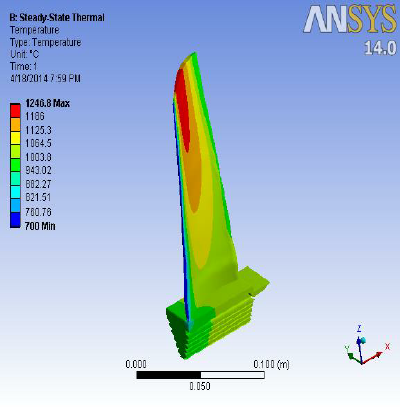
Blades must survive both centrifugal forces and thermal stresses.
The choice of materials is therefore critical in designing a turbogenerator.
Silicon Carbide is a good material choice, used in jet turbines at up to 1700K temperatures. Nickel-based superalloys are another option, retaining their strength at up to 70% of their melting temperature, but they are much denser.
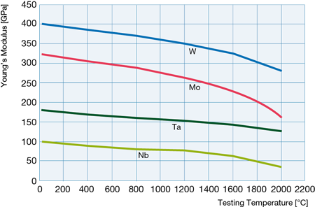
Tungsten-based alloys would obtain the best strength at 2273K+ temperatures. It is very dense though, which would increase turbine mass.
If we want even higher temperatures, we need to use active cooling of the turbine blades and ceramic materials (such as hafnium carbide). This allows us to reach 2500K or better operating temperatures.
There are also other considerations.
Only the first turbine stage really handles high temperatures.
We aim for a high specific power. This means reducing the mass of the equipment required to handle a certain level of heat input while maximizing efficiency by using a high temperature gradient. High pressure ratios are therefore also necessary, as they allow a large pressure (and temperature) drop in the turbine.
We also want a higher rather than lower turbine exhaust temperature. This is because all waste heat must be radiated using radiators, and their performance rises by the power ^4 with increasing operating temperature. For example, if the turbine releases gases at 600K instead of 400K, it allows for radiators that are over five times smaller and lighter.
Modern Brayton cycle example
We will be using existing technology for this example.

Solar receiver.
As in previous 'modern' examples, we will be using a concentrated solar power set-up, where large parabolic surfaces of a thin, reflective material, such as Mylar, is used to focus sunlight onto a solid heat exchanger.
A 10000x solar concentration means that 10000m^2 of reflectors will focus sunlight onto 1m^2 of heat exchanger.

Possible configuration of solar concentrators.
Mylar is 98% reflective. If the reflectors have a mass of 7 grams per square meter, as solar sails have demonstrated, then this means that 70kg of reflectors will deliver 1367*0.98*10000: 13.4MW of solar power at an average power density of 191.4kW/kg.
The heat exchanger we will be using is made of tungsten, and we will heat it to a temperature of 2500K. It has a very high heat tolerance and high emissivity. It also has the strength to survive a high pressure flow using thin channel walls, which reduces the overall mass of the heat exchanger. 90% efficiency is expected, with 12MW of heat absorbed and the remainder re-radiated.

We will be considering a square grid of microchannels. The grid walls are thin tungsten maintained at 2500K. To maintain a constant pressure while heating the gases, the grid must be contained inside nozzles inspired by turbojet burners.
1mm thick heat exchanger fins spaced by 1mm allows for a very large effective surface area in a small, lightweight volume. The fins will mass 19.3kg/m^2. The average distance between the gas and the fins is 0.5mm.
The gas that will flow through the turbine will be a 50/50 mixture of Xenon and Helium. The Xenon makes the gas denser, which reduces the turbine rotation velocity, so the strength requirements of the turbine blades is lower and therefore makes for a lighter turbine. Helium has a high thermal conductivity, which allows for smaller heat exchanger. Both are inert, so there is no fear of oxidation of the turbine materials. It has a molar mass of 67g/mol, a heat capacity of 2596J/kg/K and a thermal conductivity of 0.29W/mK (Xenon does not contribute much), based on figures from here.
Using the this distance, the temperature gradient and the thermal conductivity of the gas mix, we can calculate the heat transfer rate.
Heat transfer rate: Thermal conductivity * Temp. Gradient/Fluid thickness
Heat transfer rate is in W/m^2. Thermal conductivity is in W/mK, temperature gradient in Kelvin and fluid thickness in meters. To calculate this figure, we first need to find the initial and final temperature of the gas mix as it travels through the heat exchanger.
The initial temperature here will be the temperature of the gas after leaving the compressor. The final temperature will be the maximum temperature the turbine materials can handle.
As will be calculated below, the initial temperature will be 484K and the final temperature will be 1600K. This means that the heat transfer rate is an average of 1170kW/m^2 (484K) and 522kW/m^2 (1600K), or 846kW/m^2.
Using the heat capacity of the helium-xenon mix, we can determine that 5.18kg/s mass flow rate is required to absorb the 12MW of heat. The surface area to do is 12000/846: 14.18m^2, which will mass 271kg.
The heat exchanger's power density is therefore 12000/271: 44kW/kg.
Let us now design the compressor.

We will be using an axial multi-stage transonic compressor. They are suitable for our purposes as they are very efficient and will operate in a single, carefully controlled environment.
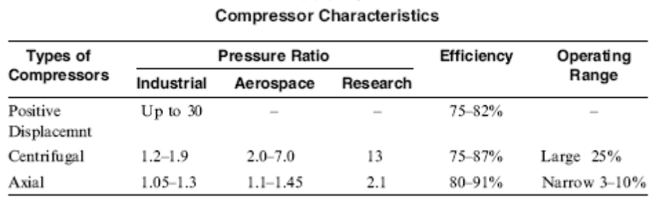
Each stage of the compressor increases the pressure of the gas mix by a certain ratio. For efficient subsonic designs, this can be at most 2.1. The effect is compounded by the number of stages.
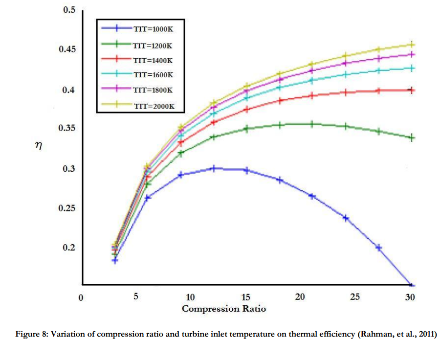
Based on the equation for isentropic expansion, we can assert that a higher pressure ratio allows for higher efficiency, as the temperature gradient in the turbine will be greater. We therefore aim for a pressure ratio of 30.
To achieve this pressure ratio, the compressor must contain (30^(1/2.1)): 5 stages. If the initial pressure is 1 bar, the final pressure is 30 bars. Normally, if the initial temperature is 300K, the gases exiting the compressor would be heated by a factor 30^(1-1/1.66): 3.866 to 1160K.
There is little margin between 1160K and the maximum operating temperature of modern turbine materials. The gas would not absorb much energy, so a large mass flow rate is required, which would lead to a larger compressor that consumes even more energy.
The solution is one employed by actual high pressure ratio engine: to split the compressor into low pressure and high pressure sections, and to cool the gases in between.

We will therefore split the 5 compressor into two parts, with an intercooler. The first part is three low pressure stages (1 bar to 9 bar) that raise the temperature from 300K to 718K. It is followed by an intercooler that reduces the gas temperature from 718K back down to 300K. The second part is two high pressure stages (9 bar to 30 bar) that raise the temperature from 300K to 484K.
There is a significant difference between 484K and 1160K!
Using the energy contained in the gases, we can calculate the work done by the compressor. The low pressure compressor raises the gas temperature from 300K (779kJ/kg) to 718K (1864kJ/kg). Since the mass flow rate is 2.89kg/s, this translates to a power consumption of 3.14MW. The intercooler then has to get rid of 3.14MW of heat. The high pressure compressor raises the gas temperature from 300K to 484K (1256kJ/kg), which requires an input of 0.48MW.
We can expect an 80% efficiency from the compressors, so the total power consumption of the compressors is 4.53MW.
Next is the turbine stage.
Based on Silicon Carbide composites developed by NASA's Glenn Research Center, we can expect a turbine to operate at 1600K without requiring any active cooling.
Turbines expand the gases they receive in multiple stages. Pressure compounding turbines lower the gas pressure without changing the gas velocity much.
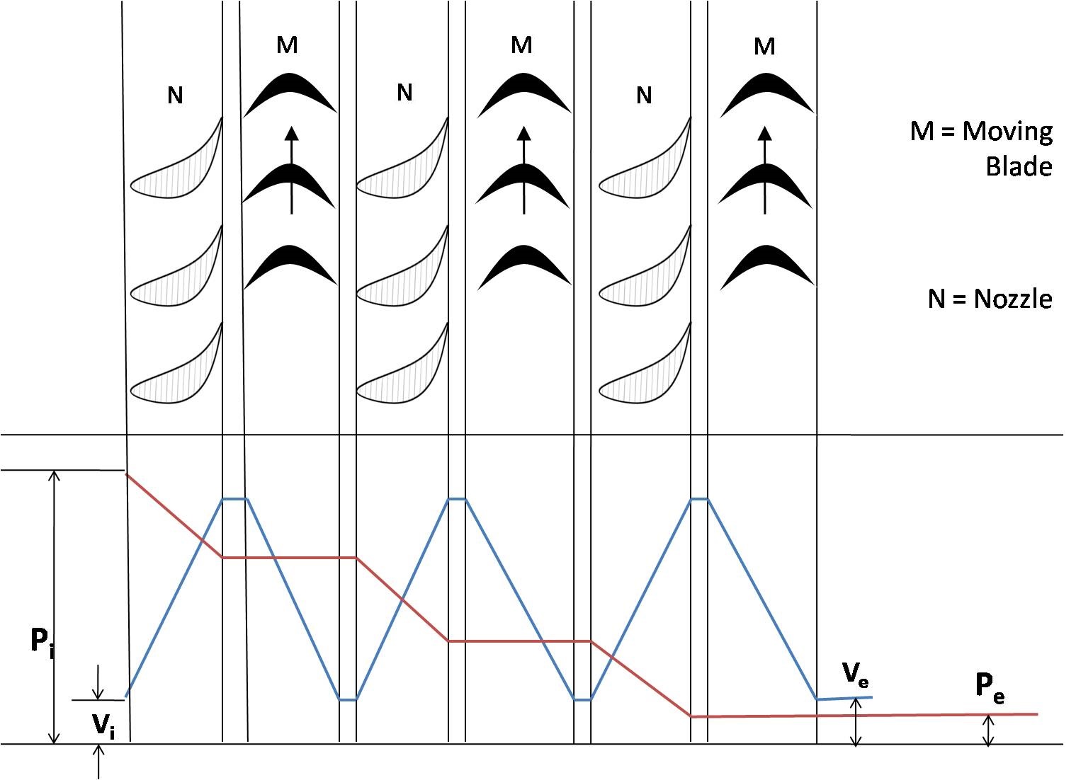
Pressure compounding impulse turbine.
We will use a turbine pressure ratio of 5.5. Only two stages are required to expand the gas from 30 bars back down to 1 bar.
The temperature drop that accompanies that pressure change is by a factor 30^(1-1/1.66): 3.866, from 1600K to 413K.
The turbine reduces the thermal energy in the gas from 4153kJ/kg (1600K) to 1085kJ/kg (418K). It therefore should extract 8.87MW from the 2.89kg/s gas flow. However, we should only expect about 90% efficiency, for an actual figure of 7.98MW.
The exhaust gases must then be cooled down from 418K to 300K, at a rate of 0.88MW.
If we add up the power generated and consumed, we obtain a net figure of 3.45MW.
To move onto calculating an estimate of the turbine's mass, we must first estimate its dimensions. The helium-xenon gas mixture will exit the heat exchanger at Mach 1 (choked flow). The speed of sound in this mixture is 578m/s. The mass flow rate translates into a volume flow rate of 0.194m^3/s. An inlet area of 0.000336m^2 is needed to allow this flow to pass, which is a disk 0.021m wide.
However, looking at actual turbine designs, the exposed blades on the first turbine stage only represent a fraction of the total radius. The blade-to-hub ratio can be as low as 10%. This means that the first stage of the turbine is 10% blade (where gas flow) and 90% hub, so the total width is increased ten-fold and the total area a hundred-fold. The smallest turbine stage is therefore 0.21m wide for 0.336m^2.
The final stage expands by a ratio equal to the pressure ratio, like any nozzle. Therefore, the second stage must have a surface area 5.5 times larger, or 1.85m^2. This requires a width of 1.54m.
The average width of our turbine is 0.87m.
The LHTEC CTS800 is representative of modern high-performance turboshaft engines, using composite materials and being optimized for light weight. It has a similar number of stages as our design, and is 1.5 times as long as it is wide. Its density is roughly 200kg/m^3. Using these numbers, we can expect our turbine to be 159kg. The 'modern' turbine alone has a power density of 21.7kW/kg.
The turbine's shaft is connected to an electrical generator that converts mechanical energy into electricity. 7kW/kg has already been tested using current technology, at an efficiency of over 95%. The operating temperature is as high as 370K.
308mmx150mm, 24.4kg, handles 170kW.
Using that generator to handle 3.45MW of mechanical power would require a mass of 493kg. It would produce 3.28MW of electricity and 173kW of waste heat.
After the turbine and the generator comes the waste heat management systems. There are three sources of waste heat: the compressor intercooler (3.14MW@718K), the turbine exhaust (880kW@418K) and the generator (173kW@370K).

A design with multiple radiators at different temperatures.
We will use three sets of radiators:
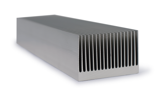
-a graphite fin radiator for the intercooler, at 718K.
-a magnesium fin radiator painted black for the turbine, at 418K.
-a magnesium fin radiator painted black for the generator, at 370K.
The high thermal conductivity of graphite and magnesium allow us to do away with any coolant loops within the radiator, which makes then very thin and with a low mass per area. Instead, coolant loops exchange heat with the fins at the attachment point at the base of the fins.
Black paint, such as a micrometer thick vapor-deposited layer of graphite flakes, is necessary to increase the emissivity of magnesium closer to 0.98.
1mm thick graphite fins work out to 2.3kg/m^2. At 718K, the radiators remove 29535W per square meter (double-sided). Handling 3.14MW of waste heat requires 106m^2 of radiators with a mass of 245kg.
1mm thick magnesiums fins have 1.7kg/m^2. At 418K, the radiators remove 3392W per square meter. 880kW of waste heat requires 259m^2 of radiators with a mass of 441kg.
The same magnesium fins at 370K remove 2083W per square meter. 173kW of waste heat requires 83m^2 of radiators with a mass of 141kg.
If we put together all these components, we obtain an output of 3.28MW of electrical power produced by 70kg of solar collectors, 271kg of heat exchanger, 159kg of turbines, 493kg of generator and 827kg of radiators for a total of 1820kg. The system power density ends up as 1.8kW/kg, although realistically it will be lower.
Advanced Brayton cycle example
We will now consider a turbogenerator made using more advanced materials and techniques.
Let's start with the same solar collector surface area of 10000m^2. However, the reflective surfaces will mass only 1 gram per square meter, for a mass of 10kg.
The critical difference between the 'advanced' and 'modern' designs is the use of carbon materials currently only being tested in laboratory environments. One such material is graphene. It has an exceptional thermal conductivity. By using a thin layer of graphene on vitreous carbon, it can also gain the strength of diamond while surviving very high temperatures.
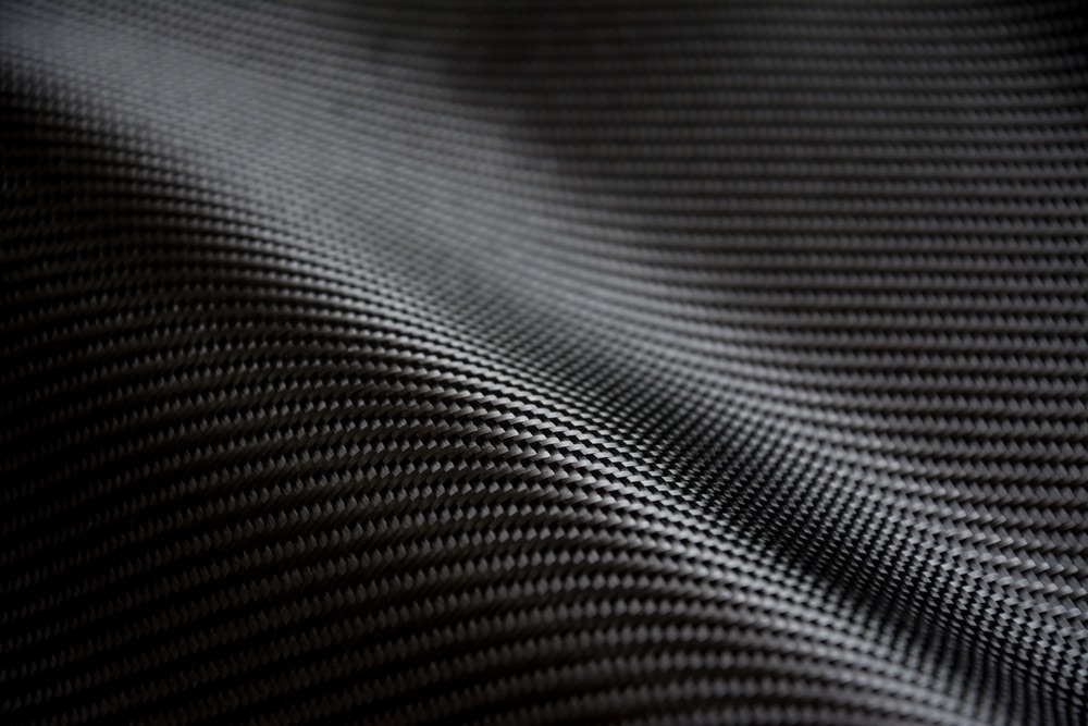
Compressed vitreous carbon weave.
This allows us to design a heat exchanger that supports higher temperatures and higher pressures with even smaller walls. We will operate the heat exchanger at 3500K. Efficiency will depend on the ratio between sunlight intensity absorbed and heat re-radiated, which will set for 95% efficiency. As before 12MW of heat is absorbed.
The plate fins will be as thin as 10 micrometers. This reduces the mass per area to 15 grams per m^2.
We will aim for a gas to reach a temperature of 3000K while leaving the heat exchanger. At such high temperatures, typical helium mixes reach extreme velocities, which would force the turbine to spin at unsustainable rates. One method of reducing the gas velocity is to increase its molar mass.
Therefore, Mercury is ideal. It has a very high molar mass of 200g/mol, so it will be 200/67: 3 times slower at the same temperature as the 67g/mol Helium-Xenon mix from the previous design. Mercury boils at just 357K, so it is unlikely that it will condense at the turbine exit.

However, the metal has a relatively poor thermal conductivity in the gaseous state, at roughly 0.02W/mK, based on this table. To compensate for this, we will use a very narrow spacing between the heat exchanger's channel walls, at 10 micrometers. The average distance between the gas and the walls falls to 5 micrometers.
The heat transfer rate in this micrometer-scale heat exchanger ranges from 2MW/m^2 at 3000K to 8.37MW/m^2 at 1208K. On average, it equals 5.18MW/m^2. The heat exchanger for 12MW of power will mass 0.034kg.
We will now work on the compressor.
Carbon fibre is ideal for compressors. It is very strong yet lightweight, meaning that fan blades and disks can reach very high RPMs. Centrifugal compressors become competitive even in large diameters. Their downside is that they become rather inefficient when used in multiple stages. The trick is to reach a very high pressure ratio within a single stage: this requires the use of supersonic centrifugal compressors.

Gas flow simulation in a centrifugal compressor.
Current test bed compressors achieve a pressure ratio of 12 with an efficiency of 90%. Improvements are likely, but we will use these numbers.
The Mercury is kept at 450K to prevent condensation. It enters the compressor at a pressure of 1 bar. At the exit, it reaches a pressure of 12 bar. As Mercury is monoatomic, the temperature increases by a factor 12^(1-1/1.66): 2.68, up to 1208K.
Mercury vapour has a heat capacity of 872J/kg/K. It enters containing 261.7kJ/kg (450K), and exits with 1053.7kJ/kg (1119K). The work done is 792kJ/kg.
To transport 12MW of heat, a mass flow rate of 12000000/((3000-1208)*872): 7.67kg/s. The compressor therefore inputs 6.08MW of work. At 95% efficiency, it consumes 6.4MW.
The turbine must expand this flow.
A radial turbine of equal pressure ratio is ideal, although thanks to high molecular weight gases, much higher is achievable.
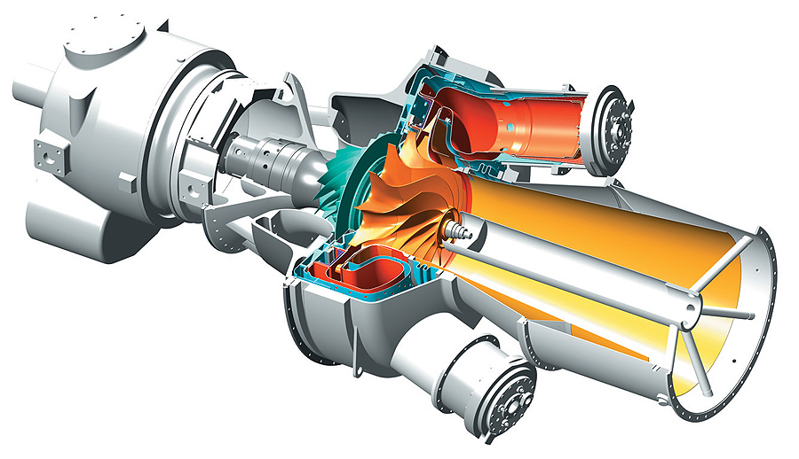
Single stage centrifugal compressor with radial turbine.
A pressure ratio of 12 allows for a temperature drop by a factor 2.68. The mercury gas is expanded from a temperature of 3000K to 1119K. It initially has 2616kJ/kg (3000K), and exits with 975kJ/kg (1208K), so the turbine extracts 1640kJ/kg.
At a mass flow rate of 7.67kg/s and 95% efficiency, this works out as a turbine output of 11.95MW.
The net power generated by the turbine is 11.95-6.4: 5.55MW
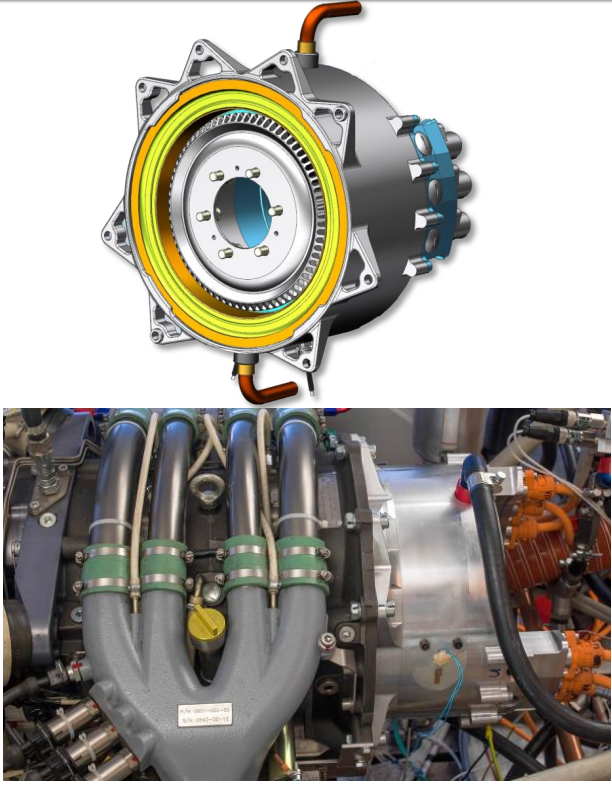
The combination of centrifugal compressor and radial turbine is commonly found in automobile turbochargers.
At the inlet, this turbine accepts 7.67kg/s of mercury at 450K. This corresponds to a volume flow rate of 1.435m^3/s. We expect this design to mass roughly 2kg, based on approximations relative to turbochargers that accept similar volume flow rates and factoring in the specific strength of the carbon materials compared to steel and nickel alloys more commonly used.
As the turbine shaft spins, it drives an electric generator. Superconducting magnets offer very high magnetic field strengths and zero-resistance current flows.
While achieving superconductivity is difficult with current magnets due to the extremely low temperatures that must be achieved (2-4K), there is research currently being done on high temperature superconductors based on copper oxide ceramics (BSCCO and YBCO). Mercury-Barium-Calcium cuprate HBSCCO can operate at temperatures as high as 133K.
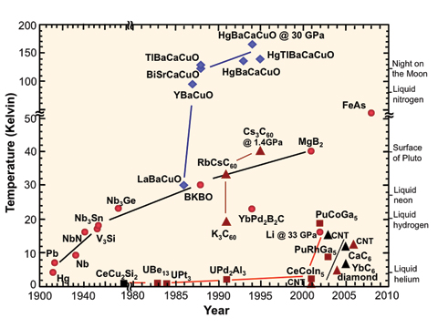
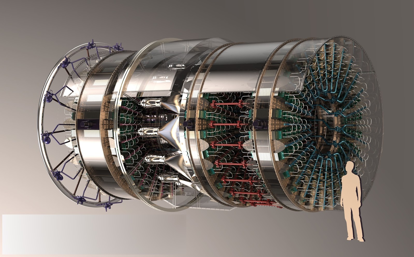
Many high temperature superconducting (HTS) electric generators are currently under development.
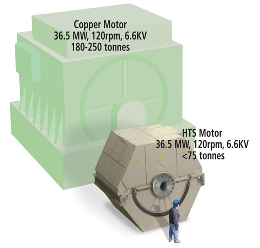
American Superconductor Corporation and Northrop Grumman 36.5MW HTS motor.
NASA research into electric aircraft that can compete in terms of output and specific power with conventional turbines provides estimates for the power densities achievable with superconducting generators: 80kW/kg or more, at 99.98% efficiency, for use on the N3-X hybrid-wing airliner.
Using carbon materials for the rotors, and statene for wiring, could easily increase this power density to 100kW/kg. With these materials, handling 5.55MW of power requires a generator mass of 55.5kg and would produce 1.11kW of waste heat at 100K.
The total amount of waste heat to be radiated out of the system is 5.47MW from the exhaust gases at 1208K, and 1.11kW from the generator at 100K.
The exhaust gas heat can be handled by a wire radiator.

Carbon fibres.
Thanks to carbon materials such as carbon fibre, we can design the radiating wires to have a high thermal conductivity, high emissivity and high strength despite being very thin.
1 micrometer wires will be used with 1750kg/m^3 density and 0.98 emissivity. They are exposed to space at 1208K. Each meter length of carbon wire has a mass of 1.375 nanograms and a surface area of 3.14*10^-6 m^2.
One million such wires can be aligned in parallel in a 1m^2 space. Interreflection reduces radiative efficiency to 70.4%. This means each square meter of microwire radiator has a mass of 1.375 grams and an effective area of 2.21m^2. At 1208K, it radiates 118.33kW/m^2. So, the power density of the microwire radiator is 190.2MW/kg.
The radiators for the turbine exhaust will mass 0.0292kg.
If those same wires were used to cool the cryogenic generators at 100K (5.6W/m^2), we would need a mass of 0.124kg.
We can now add up the mass of all these components to work out an estimate of the system power density. The advanced turbine design produces 5.55MW of power for a mass of 57.69kg, thereby achieving a power density of 96kW/kg.
Next, we will look at the Rankine cycle, as well as some rather exotic power generating schemes.
Advanced Solar Energy in Space: Part II
Brayton cycle
We commonly see the Brayton cycle used to convert heat into work in jet engines and the steam turbines of power plants. There are three main components: a compressor, a heat exchanger and a turbine. Gas is compressed to a high pressure by the compressor, then is heated by the heat exchanger. The turbine expands this gas to convert its energy into the mechanical rotation of the turbine's shaft. The latter is used to compress more gas, with the energy remaining able to be put to work. In a power plant, the remaining energy is used to spin an alternator to generate an electric current. Together, this forms a Brayton-cycle turbo-generator.
A closed cycle gas turbine adds an additional step: the exhaust gases released by the turbine are recycled back into the compressor. The gas is heated externally and is typically inert, as it is not being burnt up like in an open-cycle gas turbine. This makes it it ideal for space applications.
Let us have a look at the pressure and temperature conditions at each step of the closed Brayton cycle to understand where the turbine's power is coming from. We assume typical component efficiencies of 80% for the compressor and 90% for the turbine.
We will set Temp1 and Press1 as the temperature and pressure of the gas at the compressor's inlet. Temp 2, Press2 at the compressor's outlet, Temp3, Press3 at the turbine's inlet, Temp4, Press4 at the turbine's outlet. We will use example figures for these to make it easier to understand, in Kelvin and bars respectively. We will assume a monoatomic gas, such as helium, with a constant volume heat capacity of 3.12kJ/kg/K.
The gas starts at Temp1: 300K and Press1: 1bar. This is a warm gas at sea level pressure. It contains very little energy: 936kJ/kg.
The compressor raises the pressure to Press2: 10 bars. The gas's temperature increases by a factor determined by the following equation for isentropic expansion:
Inlet Temperature/Outlet Temperature= Pressure Ratio ^ (1 - 1/y)
The compressor increases the pressure tenfold, to the pressure ratio is 10. 'y' is the adiabatic gas constant. For simple mono-atomic gases, it is equal to 1.6.
We work out that the compressor increases the temperature by a factor 2.37. Temp2 is therefore 711K and the gas contains 2218kJ/kg. Due to the compressor's efficiency of 80%, this step consumes (2218-936)/0.8: 1602kJ/kg.
The gas then arrives at the heat exchanger. It is designed to heat up the gas at constant pressure. The gas exits the heat exchanger at Temp3: 1300K and Press3: 10bar, reaching 4056kJ/kg.The heat exchanger grants an energy increase of (4056-2218): 1838kJ/kg.
The turbine is the most critical component. Here, the gas is expanded back to a pressure of 1bar, so Press4: 1 bar. Isentropic expansion causes a temperature drop. Using the same equation as above, we know that a tenfold pressure decrease will reduce the temperature by a factor 2.37. Therefore, the gas exits the turbine at Temp4: 1300/2.37 = 548K. It falls to 1710kJ/kg. Because the turbine is 90% efficient, it extracts only (4056-1710)*0.9: 2111kJ/kg.
This is exhaust at Temp4 and Press4 must then be cooled down back to initial conditions, of Temp1 and Press1, using a radiator.
The find out the net energy extracted by the turbine, it is easiest to calculate the difference between the energy consumed by the compressor and the energy extracted by the turbine. This amounts to 2111-1602: 509kJ/kg.
Compare this to the energy granted by the heat exchanger to find the overall efficiency.
509/1838: 0.2777 or 27.8%
Technically, gas pressure also contains energy, but in a closed cycle, what is spent in the compressor to increase the pressure is regained in the turbine when it expands the gas.
To extract more power and increase overall efficiency, we can immediately understand that we need a higher temperature gradient. As we have seen in Part 1 of Advanced Solar Energy in Space, it is possible to design a heat exchanger that reaches thousands of Kelvin under concentrated sunlight. We will use this as the heat source for our space-based turbogenerator, as has been considered before by NASA.
However, we must make sure that the turbine blades are able to survive the Temp3 conditions. While there are many materials that do not melt even at very high temperature, there are few that remain strong enough to rotate at thousands of RPM without deforming under those same conditions.
Strength/Temperature curve for a Nickel superalloy.
Shown above is the yield strength of a Ni-Cr-W-Al-Ti-Fe-Si-C-B (Nickel, Chromium, Tungsten, Aluminium, Titanium, Iron, Silicon, Carbon, Boron) superalloy. It is designed to survive for 100000 hours under conditions of high stress (1000 bars) and high temperature (1023K). Looking at the graph, we notice that it retains most of its strength up to about 750oC, making it ideal for the conditions it was designed for. However, if we used it in the turbine we used as an example above, operating at 1300K (1027oC), it would have a strength reduced by over 80% compared to what it was designed for!
Blades must survive both centrifugal forces and thermal stresses.
The choice of materials is therefore critical in designing a turbogenerator.
Silicon Carbide is a good material choice, used in jet turbines at up to 1700K temperatures. Nickel-based superalloys are another option, retaining their strength at up to 70% of their melting temperature, but they are much denser.
Tungsten-based alloys would obtain the best strength at 2273K+ temperatures. It is very dense though, which would increase turbine mass.
If we want even higher temperatures, we need to use active cooling of the turbine blades and ceramic materials (such as hafnium carbide). This allows us to reach 2500K or better operating temperatures.
There are also other considerations.
Only the first turbine stage really handles high temperatures.
We aim for a high specific power. This means reducing the mass of the equipment required to handle a certain level of heat input while maximizing efficiency by using a high temperature gradient. High pressure ratios are therefore also necessary, as they allow a large pressure (and temperature) drop in the turbine.
We also want a higher rather than lower turbine exhaust temperature. This is because all waste heat must be radiated using radiators, and their performance rises by the power ^4 with increasing operating temperature. For example, if the turbine releases gases at 600K instead of 400K, it allows for radiators that are over five times smaller and lighter.
Modern Brayton cycle example
We will be using existing technology for this example.
Solar receiver.
As in previous 'modern' examples, we will be using a concentrated solar power set-up, where large parabolic surfaces of a thin, reflective material, such as Mylar, is used to focus sunlight onto a solid heat exchanger.
A 10000x solar concentration means that 10000m^2 of reflectors will focus sunlight onto 1m^2 of heat exchanger.
Possible configuration of solar concentrators.
Mylar is 98% reflective. If the reflectors have a mass of 7 grams per square meter, as solar sails have demonstrated, then this means that 70kg of reflectors will deliver 1367*0.98*10000: 13.4MW of solar power at an average power density of 191.4kW/kg.
The heat exchanger we will be using is made of tungsten, and we will heat it to a temperature of 2500K. It has a very high heat tolerance and high emissivity. It also has the strength to survive a high pressure flow using thin channel walls, which reduces the overall mass of the heat exchanger. 90% efficiency is expected, with 12MW of heat absorbed and the remainder re-radiated.
We will be considering a square grid of microchannels. The grid walls are thin tungsten maintained at 2500K. To maintain a constant pressure while heating the gases, the grid must be contained inside nozzles inspired by turbojet burners.
1mm thick heat exchanger fins spaced by 1mm allows for a very large effective surface area in a small, lightweight volume. The fins will mass 19.3kg/m^2. The average distance between the gas and the fins is 0.5mm.
The gas that will flow through the turbine will be a 50/50 mixture of Xenon and Helium. The Xenon makes the gas denser, which reduces the turbine rotation velocity, so the strength requirements of the turbine blades is lower and therefore makes for a lighter turbine. Helium has a high thermal conductivity, which allows for smaller heat exchanger. Both are inert, so there is no fear of oxidation of the turbine materials. It has a molar mass of 67g/mol, a heat capacity of 2596J/kg/K and a thermal conductivity of 0.29W/mK (Xenon does not contribute much), based on figures from here.
Using the this distance, the temperature gradient and the thermal conductivity of the gas mix, we can calculate the heat transfer rate.
Heat transfer rate: Thermal conductivity * Temp. Gradient/Fluid thickness
Heat transfer rate is in W/m^2. Thermal conductivity is in W/mK, temperature gradient in Kelvin and fluid thickness in meters. To calculate this figure, we first need to find the initial and final temperature of the gas mix as it travels through the heat exchanger.
The initial temperature here will be the temperature of the gas after leaving the compressor. The final temperature will be the maximum temperature the turbine materials can handle.
As will be calculated below, the initial temperature will be 484K and the final temperature will be 1600K. This means that the heat transfer rate is an average of 1170kW/m^2 (484K) and 522kW/m^2 (1600K), or 846kW/m^2.
Using the heat capacity of the helium-xenon mix, we can determine that 5.18kg/s mass flow rate is required to absorb the 12MW of heat. The surface area to do is 12000/846: 14.18m^2, which will mass 271kg.
The heat exchanger's power density is therefore 12000/271: 44kW/kg.
Let us now design the compressor.
We will be using an axial multi-stage transonic compressor. They are suitable for our purposes as they are very efficient and will operate in a single, carefully controlled environment.
Each stage of the compressor increases the pressure of the gas mix by a certain ratio. For efficient subsonic designs, this can be at most 2.1. The effect is compounded by the number of stages.
Based on the equation for isentropic expansion, we can assert that a higher pressure ratio allows for higher efficiency, as the temperature gradient in the turbine will be greater. We therefore aim for a pressure ratio of 30.
To achieve this pressure ratio, the compressor must contain (30^(1/2.1)): 5 stages. If the initial pressure is 1 bar, the final pressure is 30 bars. Normally, if the initial temperature is 300K, the gases exiting the compressor would be heated by a factor 30^(1-1/1.66): 3.866 to 1160K.
There is little margin between 1160K and the maximum operating temperature of modern turbine materials. The gas would not absorb much energy, so a large mass flow rate is required, which would lead to a larger compressor that consumes even more energy.
The solution is one employed by actual high pressure ratio engine: to split the compressor into low pressure and high pressure sections, and to cool the gases in between.
We will therefore split the 5 compressor into two parts, with an intercooler. The first part is three low pressure stages (1 bar to 9 bar) that raise the temperature from 300K to 718K. It is followed by an intercooler that reduces the gas temperature from 718K back down to 300K. The second part is two high pressure stages (9 bar to 30 bar) that raise the temperature from 300K to 484K.
There is a significant difference between 484K and 1160K!
Using the energy contained in the gases, we can calculate the work done by the compressor. The low pressure compressor raises the gas temperature from 300K (779kJ/kg) to 718K (1864kJ/kg). Since the mass flow rate is 2.89kg/s, this translates to a power consumption of 3.14MW. The intercooler then has to get rid of 3.14MW of heat. The high pressure compressor raises the gas temperature from 300K to 484K (1256kJ/kg), which requires an input of 0.48MW.
We can expect an 80% efficiency from the compressors, so the total power consumption of the compressors is 4.53MW.
Next is the turbine stage.
Based on Silicon Carbide composites developed by NASA's Glenn Research Center, we can expect a turbine to operate at 1600K without requiring any active cooling.
Turbines expand the gases they receive in multiple stages. Pressure compounding turbines lower the gas pressure without changing the gas velocity much.
Pressure compounding impulse turbine.
We will use a turbine pressure ratio of 5.5. Only two stages are required to expand the gas from 30 bars back down to 1 bar.
The temperature drop that accompanies that pressure change is by a factor 30^(1-1/1.66): 3.866, from 1600K to 413K.
The turbine reduces the thermal energy in the gas from 4153kJ/kg (1600K) to 1085kJ/kg (418K). It therefore should extract 8.87MW from the 2.89kg/s gas flow. However, we should only expect about 90% efficiency, for an actual figure of 7.98MW.
The exhaust gases must then be cooled down from 418K to 300K, at a rate of 0.88MW.
If we add up the power generated and consumed, we obtain a net figure of 3.45MW.
To move onto calculating an estimate of the turbine's mass, we must first estimate its dimensions. The helium-xenon gas mixture will exit the heat exchanger at Mach 1 (choked flow). The speed of sound in this mixture is 578m/s. The mass flow rate translates into a volume flow rate of 0.194m^3/s. An inlet area of 0.000336m^2 is needed to allow this flow to pass, which is a disk 0.021m wide.
However, looking at actual turbine designs, the exposed blades on the first turbine stage only represent a fraction of the total radius. The blade-to-hub ratio can be as low as 10%. This means that the first stage of the turbine is 10% blade (where gas flow) and 90% hub, so the total width is increased ten-fold and the total area a hundred-fold. The smallest turbine stage is therefore 0.21m wide for 0.336m^2.
The final stage expands by a ratio equal to the pressure ratio, like any nozzle. Therefore, the second stage must have a surface area 5.5 times larger, or 1.85m^2. This requires a width of 1.54m.
The average width of our turbine is 0.87m.
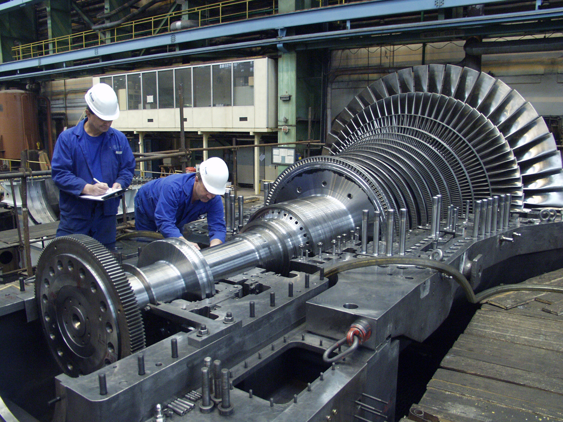
The LHTEC CTS800 is representative of modern high-performance turboshaft engines, using composite materials and being optimized for light weight. It has a similar number of stages as our design, and is 1.5 times as long as it is wide. Its density is roughly 200kg/m^3. Using these numbers, we can expect our turbine to be 159kg. The 'modern' turbine alone has a power density of 21.7kW/kg.
The turbine's shaft is connected to an electrical generator that converts mechanical energy into electricity. 7kW/kg has already been tested using current technology, at an efficiency of over 95%. The operating temperature is as high as 370K.
308mmx150mm, 24.4kg, handles 170kW.
Using that generator to handle 3.45MW of mechanical power would require a mass of 493kg. It would produce 3.28MW of electricity and 173kW of waste heat.
After the turbine and the generator comes the waste heat management systems. There are three sources of waste heat: the compressor intercooler (3.14MW@718K), the turbine exhaust (880kW@418K) and the generator (173kW@370K).
A design with multiple radiators at different temperatures.
We will use three sets of radiators:
-a graphite fin radiator for the intercooler, at 718K.
-a magnesium fin radiator painted black for the turbine, at 418K.
-a magnesium fin radiator painted black for the generator, at 370K.
The high thermal conductivity of graphite and magnesium allow us to do away with any coolant loops within the radiator, which makes then very thin and with a low mass per area. Instead, coolant loops exchange heat with the fins at the attachment point at the base of the fins.
Black paint, such as a micrometer thick vapor-deposited layer of graphite flakes, is necessary to increase the emissivity of magnesium closer to 0.98.
1mm thick graphite fins work out to 2.3kg/m^2. At 718K, the radiators remove 29535W per square meter (double-sided). Handling 3.14MW of waste heat requires 106m^2 of radiators with a mass of 245kg.
1mm thick magnesiums fins have 1.7kg/m^2. At 418K, the radiators remove 3392W per square meter. 880kW of waste heat requires 259m^2 of radiators with a mass of 441kg.
The same magnesium fins at 370K remove 2083W per square meter. 173kW of waste heat requires 83m^2 of radiators with a mass of 141kg.
If we put together all these components, we obtain an output of 3.28MW of electrical power produced by 70kg of solar collectors, 271kg of heat exchanger, 159kg of turbines, 493kg of generator and 827kg of radiators for a total of 1820kg. The system power density ends up as 1.8kW/kg, although realistically it will be lower.
Advanced Brayton cycle example
We will now consider a turbogenerator made using more advanced materials and techniques.
Let's start with the same solar collector surface area of 10000m^2. However, the reflective surfaces will mass only 1 gram per square meter, for a mass of 10kg.
The critical difference between the 'advanced' and 'modern' designs is the use of carbon materials currently only being tested in laboratory environments. One such material is graphene. It has an exceptional thermal conductivity. By using a thin layer of graphene on vitreous carbon, it can also gain the strength of diamond while surviving very high temperatures.
Compressed vitreous carbon weave.
This allows us to design a heat exchanger that supports higher temperatures and higher pressures with even smaller walls. We will operate the heat exchanger at 3500K. Efficiency will depend on the ratio between sunlight intensity absorbed and heat re-radiated, which will set for 95% efficiency. As before 12MW of heat is absorbed.
The plate fins will be as thin as 10 micrometers. This reduces the mass per area to 15 grams per m^2.
We will aim for a gas to reach a temperature of 3000K while leaving the heat exchanger. At such high temperatures, typical helium mixes reach extreme velocities, which would force the turbine to spin at unsustainable rates. One method of reducing the gas velocity is to increase its molar mass.
Therefore, Mercury is ideal. It has a very high molar mass of 200g/mol, so it will be 200/67: 3 times slower at the same temperature as the 67g/mol Helium-Xenon mix from the previous design. Mercury boils at just 357K, so it is unlikely that it will condense at the turbine exit.
However, the metal has a relatively poor thermal conductivity in the gaseous state, at roughly 0.02W/mK, based on this table. To compensate for this, we will use a very narrow spacing between the heat exchanger's channel walls, at 10 micrometers. The average distance between the gas and the walls falls to 5 micrometers.
The heat transfer rate in this micrometer-scale heat exchanger ranges from 2MW/m^2 at 3000K to 8.37MW/m^2 at 1208K. On average, it equals 5.18MW/m^2. The heat exchanger for 12MW of power will mass 0.034kg.
We will now work on the compressor.
Carbon fibre is ideal for compressors. It is very strong yet lightweight, meaning that fan blades and disks can reach very high RPMs. Centrifugal compressors become competitive even in large diameters. Their downside is that they become rather inefficient when used in multiple stages. The trick is to reach a very high pressure ratio within a single stage: this requires the use of supersonic centrifugal compressors.
Gas flow simulation in a centrifugal compressor.
Current test bed compressors achieve a pressure ratio of 12 with an efficiency of 90%. Improvements are likely, but we will use these numbers.
The Mercury is kept at 450K to prevent condensation. It enters the compressor at a pressure of 1 bar. At the exit, it reaches a pressure of 12 bar. As Mercury is monoatomic, the temperature increases by a factor 12^(1-1/1.66): 2.68, up to 1208K.
Mercury vapour has a heat capacity of 872J/kg/K. It enters containing 261.7kJ/kg (450K), and exits with 1053.7kJ/kg (1119K). The work done is 792kJ/kg.
To transport 12MW of heat, a mass flow rate of 12000000/((3000-1208)*872): 7.67kg/s. The compressor therefore inputs 6.08MW of work. At 95% efficiency, it consumes 6.4MW.
The turbine must expand this flow.
A radial turbine of equal pressure ratio is ideal, although thanks to high molecular weight gases, much higher is achievable.
Single stage centrifugal compressor with radial turbine.
A pressure ratio of 12 allows for a temperature drop by a factor 2.68. The mercury gas is expanded from a temperature of 3000K to 1119K. It initially has 2616kJ/kg (3000K), and exits with 975kJ/kg (1208K), so the turbine extracts 1640kJ/kg.
At a mass flow rate of 7.67kg/s and 95% efficiency, this works out as a turbine output of 11.95MW.
The net power generated by the turbine is 11.95-6.4: 5.55MW
The combination of centrifugal compressor and radial turbine is commonly found in automobile turbochargers.
At the inlet, this turbine accepts 7.67kg/s of mercury at 450K. This corresponds to a volume flow rate of 1.435m^3/s. We expect this design to mass roughly 2kg, based on approximations relative to turbochargers that accept similar volume flow rates and factoring in the specific strength of the carbon materials compared to steel and nickel alloys more commonly used.
As the turbine shaft spins, it drives an electric generator. Superconducting magnets offer very high magnetic field strengths and zero-resistance current flows.
While achieving superconductivity is difficult with current magnets due to the extremely low temperatures that must be achieved (2-4K), there is research currently being done on high temperature superconductors based on copper oxide ceramics (BSCCO and YBCO). Mercury-Barium-Calcium cuprate HBSCCO can operate at temperatures as high as 133K.
Many high temperature superconducting (HTS) electric generators are currently under development.
American Superconductor Corporation and Northrop Grumman 36.5MW HTS motor.
NASA research into electric aircraft that can compete in terms of output and specific power with conventional turbines provides estimates for the power densities achievable with superconducting generators: 80kW/kg or more, at 99.98% efficiency, for use on the N3-X hybrid-wing airliner.
Using carbon materials for the rotors, and statene for wiring, could easily increase this power density to 100kW/kg. With these materials, handling 5.55MW of power requires a generator mass of 55.5kg and would produce 1.11kW of waste heat at 100K.
The total amount of waste heat to be radiated out of the system is 5.47MW from the exhaust gases at 1208K, and 1.11kW from the generator at 100K.
The exhaust gas heat can be handled by a wire radiator.
Carbon fibres.
Thanks to carbon materials such as carbon fibre, we can design the radiating wires to have a high thermal conductivity, high emissivity and high strength despite being very thin.
1 micrometer wires will be used with 1750kg/m^3 density and 0.98 emissivity. They are exposed to space at 1208K. Each meter length of carbon wire has a mass of 1.375 nanograms and a surface area of 3.14*10^-6 m^2.
One million such wires can be aligned in parallel in a 1m^2 space. Interreflection reduces radiative efficiency to 70.4%. This means each square meter of microwire radiator has a mass of 1.375 grams and an effective area of 2.21m^2. At 1208K, it radiates 118.33kW/m^2. So, the power density of the microwire radiator is 190.2MW/kg.
The radiators for the turbine exhaust will mass 0.0292kg.
If those same wires were used to cool the cryogenic generators at 100K (5.6W/m^2), we would need a mass of 0.124kg.
We can now add up the mass of all these components to work out an estimate of the system power density. The advanced turbine design produces 5.55MW of power for a mass of 57.69kg, thereby achieving a power density of 96kW/kg.
Next, we will look at the Rankine cycle, as well as some rather exotic power generating schemes.